
- Home
- Our Company
- Latest News
- Pin-in-Paste LED vs Traditional Through-Hole LED Indicators: What Manufacturing Engineers Need to Know
Pin-in-Paste LED vs Traditional Through-Hole LED Indicators: What Manufacturing Engineers Need to Know
Quick Answer: What Is the Difference?
A traditional through-hole LED indicator uses pins inserted through plated holes in the PCB and is typically soldered using wave soldering, selective soldering, or manual soldering.
A Pin-in-Paste LED indicator also uses through-hole pins, but solder paste is printed into or around the plated through holes before placement, allowing the component to be soldered during the SMT reflow process.
Two Through-Hole Indicator Approaches, Different Assembly Paths
Both options use through-hole pins inserted into plated holes. The main difference is how the indicator fits into the soldering process and whether a separate post-reflow soldering step is still required.
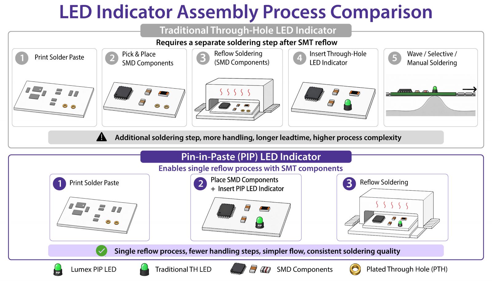
▲ Pin-in-Paste LED indicators keep the through-hole format while allowing soldering through the SMT reflow process.
Traditional Through-Hole
Stable Indicator Positioning with a Separate Soldering Step
A traditional through-hole LED indicator uses pins that pass through plated holes in the PCB. This style is common in control panels, industrial equipment, instruments, appliances, power devices, and other products where the indicator must align with a front panel or provide a clear visual signal.
Traditional through-hole indicators can be a strong choice when the product already includes a through-hole soldering process or when the mechanical design benefits from pins passing through the PCB.
Typical assembly path
Pin-in-Paste
Through-Hole Indicator Format Designed for SMT Reflow Flow
Pin-in-Paste, also known as PIP or Paste-in-Hole, is an assembly method that allows selected through-hole components to be soldered during the SMT reflow process.
For a PIP LED indicator, solder paste is printed onto the plated through holes. The indicator pins are then inserted into those holes, and the solder paste melts during reflow to form the solder joint between the pin and the plated hole.
Typical assembly path
PIP Compatibility Reminder
Not every through-hole LED indicator can be used in a Pin-in-Paste process. Reflow soldering exposes the component body to higher temperatures than many standard through-hole LED indicators were designed to tolerate.
Manufacturing teams should not assume that a standard through-hole LED can simply be moved into a PIP process. The LED indicator should be selected and validated for Pin-in-Paste compatibility.
Housing Temperature Resistance
The indicator body must tolerate the reflow profile without deformation, blistering, or melting.
LED Structure Stability
High reflow heat can stress LED package structures if the part is not designed for this process.
Key Manufacturing Differences Between PIP and Traditional Through-Hole Indicators
Select each topic below to compare how the same through-hole indicator concept can lead to different soldering methods, process impact, validation checks, and product-fit decisions.
Mounting and Assembly Route
Uses through-hole pins inserted into plated holes, but often remains outside the main SMT reflow flow.
Also uses through-hole pins inserted into plated holes, but is selected to support soldering through the SMT reflow process.
Soldering Method and Joint Formation
Typically relies on wave soldering, selective soldering, or manual soldering after SMT reflow.
Uses solder paste printed into or around plated through holes. During reflow, the paste melts and forms the solder joint between the pin and the plated hole.
Reflow Profile and Compatibility
May avoid full SMT reflow exposure if the LED indicator is inserted and soldered after reflow.
The indicator must tolerate the actual reflow profile, including peak temperature, time above liquidus, and repeated reflow cycles where applicable.
Best Fit and Placement Checks
Can be suitable for products already using through-hole soldering, low-volume builds, or validated legacy designs.
Can be suitable for mixed SMT boards that still need through-hole LED indicator positioning, height, panel alignment, or mechanical stability.
Lumex PIP Product Options
Reflow-Compatible LED Indicator Examples
The following Lumex PIP indicator examples show how different LED colors, package formats, and reflow profile requirements can be considered during product selection.
Separate LED option: The LED lamps used in these indicator assemblies are also available for separate purchase.
SSF-H431YRGBW3-MT
4-LED vertical PIP indicator
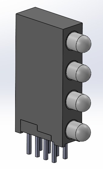
Colors: Y/R bicolor, yellow green, blue
Soldering profile: 250℃ / 10 sec, 217℃ / 60–150 sec, 2 times reflow process
Package: 4.5(W) × 20.30(H) × 10.70(D) mm
SSF-H131RW3-MR
1-level red PIP indicator
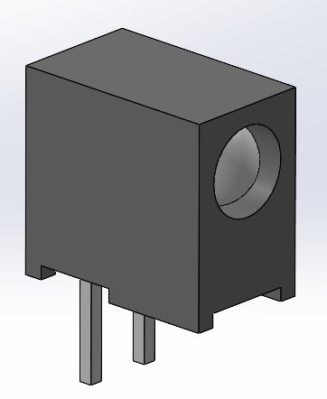
Color: Red, 630 nm
Soldering profile: 250℃ / 10 sec, 217℃ / 60–150 sec, 2 times reflow process
Package: 7.3(H) × 4.6(W) × 7.7(D) mm
SSF-H131GW3-MR
1-level green PIP indicator
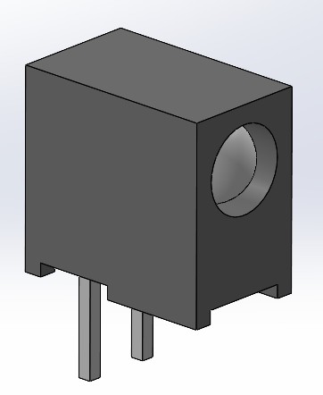
Color: Green, 575 nm
Soldering profile: 260℃ / 10 sec, 217℃ / 60–150 sec, 2 times reflow process
Package: 7.3(H) × 4.6(W) × 7.7(D) mm
When Traditional Through-Hole LED Indicators Still Make Sense
Traditional through-hole LED indicators remain a practical choice in many products. They may be the better option when the assembly process already includes wave soldering or selective soldering, when the product does not require SMT-only processing, or when the existing design is already validated and cost-effective.
They can also make sense for lower-volume builds where manual soldering is acceptable, or for legacy designs where changing the LED indicator and PCB layout would create unnecessary qualification work.
The best choice depends on the full manufacturing context, not only the component itself.
Selection Checklist for Manufacturing Engineers
Before selecting a PIP LED indicator, review both component requirements and process conditions.
Common Mistakes to Avoid
Click each item to review common selection and process risks when evaluating PIP LED indicators.
Assuming Any Through-Hole LED Can Be Used for PIP
A standard through-hole LED indicator may not survive reflow soldering. Always confirm that the selected indicator is suitable for the intended PIP process.
Only Checking Electrical Specifications
Forward voltage, current, color, and brightness are important, but they are not enough. For PIP selection, mechanical fit and process compatibility are just as important.
Ignoring Solder Paste Volume
PIP depends on the right solder paste deposit. Manufacturing teams should work with PCB layout, stencil design, and process engineering to avoid insufficient solder or excessive solder around the holes.
Forgetting the Front Panel Relationship
An LED indicator can pass electrical testing and still fail the product experience if it does not align correctly with the panel opening. Check the full stack-up early.
LED Indicator Support
How Lumex Can Support LED Indicator Selection
Lumex offers a broad range of LED indicator options for product teams that need practical choices for visibility, mounting style, color, size, and assembly requirements.
For projects evaluating Pin-in-Paste LED indicators, Lumex can help customers discuss product options that fit reflow-compatible assembly goals, panel alignment needs, and application requirements.
Whether the project requires a traditional through-hole indicator, a Pin-in-Paste option, a right-angle indicator, a vertical indicator, or a custom discussion around appearance and mounting, the selection should begin with both the product design and the manufacturing process in mind.
Contact Lumex to discuss LED indicator options, sample needs, or customization requirements for your next project.
Contact Lumex for LED Indicator Support