
LUMEX TOUCH AND RGB DISPLAY SOLUTIONS
Make every interaction visible.
A touch can select a function. A change in color can show what happens next. Explore Lumex modules that bring illuminated input and RGB status indication to front panels and electronic controls.
Touch + illumination
One integrated button module
24-bit RGB
Color control for the ring display
GPIO + serial data
Control interfaces defined by module
Touch customization
Discuss icons, LED color and mode
Put touch and illumination in the same control.
LDM-TPC11079D
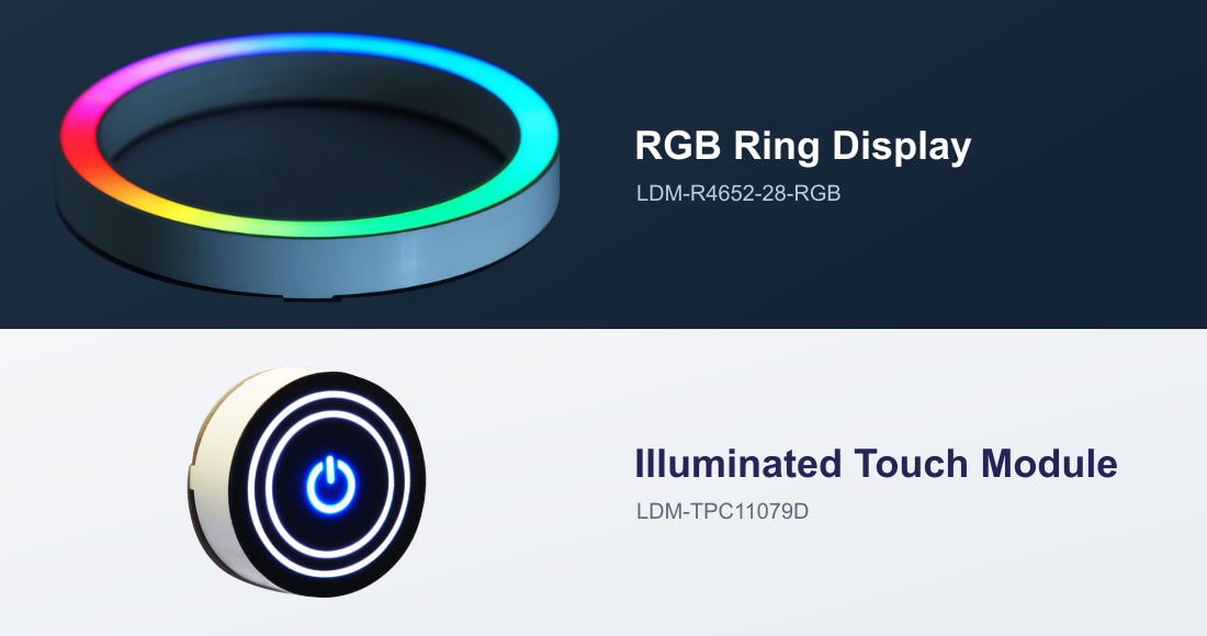
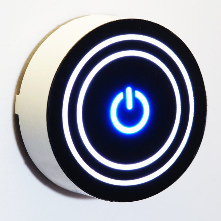
The LDM-TPC11079D combines a capacitive touch switch and LED illumination in a 28.0 mm round module. It gives designers an illuminated control point for functions such as power, mode selection or a user command.
With three connections for supply, ground and signal output, the module provides a GPIO signal for the host controller. Review the published output patterns and the controller’s input requirements when defining how each touch is detected and interpreted.
The illuminated rings and central symbol provide a visible indication at the point of interaction. Review the desired touch behavior and illuminated states together when defining the control.
Explore the illuminated appearance.
Illuminated rings and a central power symbol give the control several possible appearances. These five product photographs show different ring and icon illumination states. The selected operating mode determines the touch sequence and signal output.
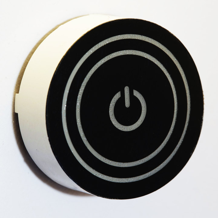
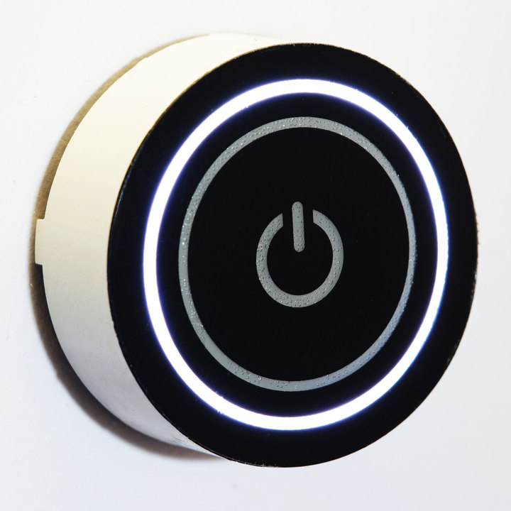
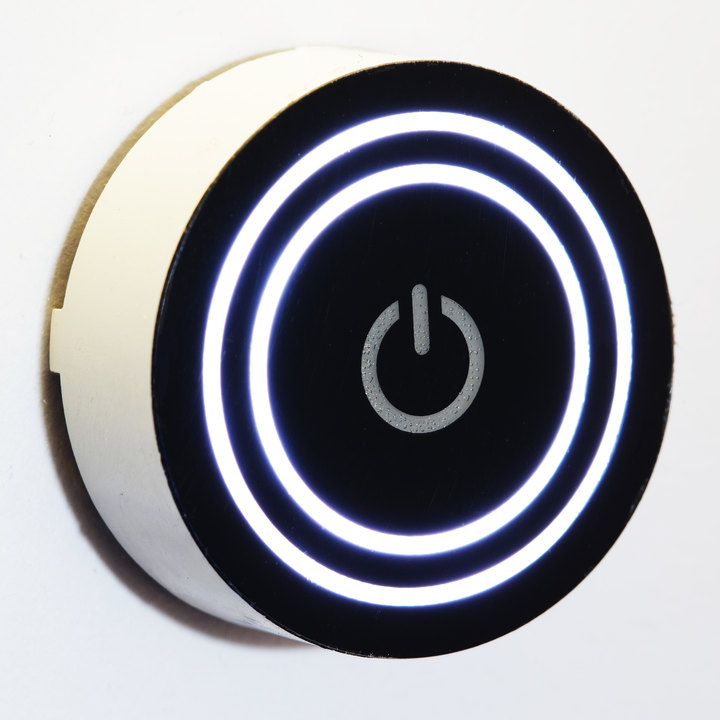
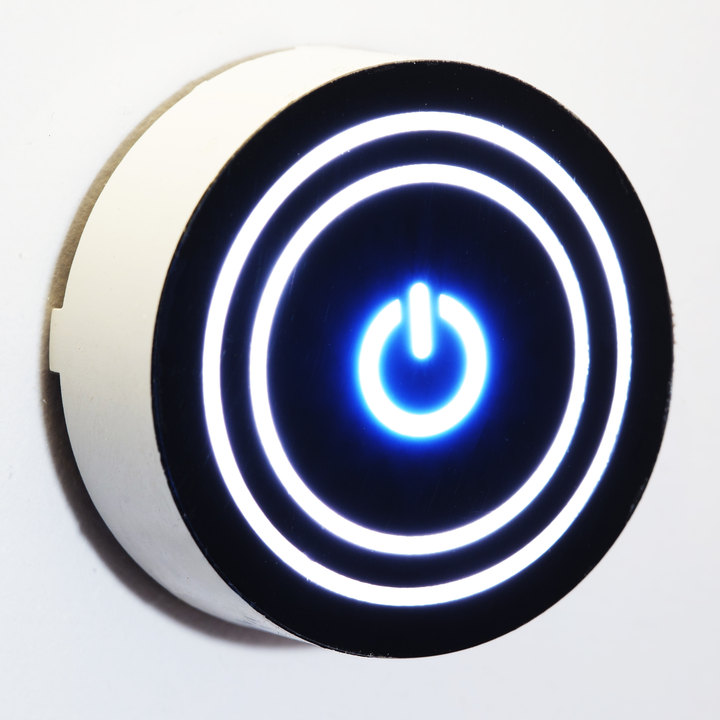
Design the icon around the function. The power symbol shown is one example. Discuss custom illuminated icons and faceplate designs with Lumex to match your product’s functions and appearance, along with LED color, operating mode and signal output.
Turn color into useful feedback.
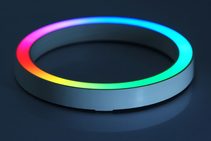
LDM-R4652-28-RGB
The LDM-R4652-28-RGB adds a circular RGB indication area to the interface. Its 54.30 mm outer diameter and open-center format make it an option for illuminated knobs, controls and status indicators.
A single-wire data interface carries the RGB commands. Separate data-input and data-output connections support passing data onward, while power and ground have their own pins. The datasheet defines the transfer format and timing for the controller design.
Its 24-bit RGB data contains 8 bits per color channel: 256 digital levels each for red, green and blue. That provides 16,777,216 possible RGB code combinations for defining colors and brightness in the product interface.
Make operating states recognizable
Define colors for the states your product needs to show, such as ready, running or attention. Review the color assignments alongside the product’s operating sequence and other indicators.
Keep the interface focused
A color change can communicate a change of state without adding another numeric display. Coordinate the indication with the product’s labels, controls and intended operating sequence.
Where these modules fit in your interface.
Start with the function your interface needs: an illuminated touch input, a color-based status indicator or a control with several visible states. The following design concepts connect those requirements to the modules’ documented functions.
Illuminated touch buttons
Touch input and an illuminated symbol
Consider the LDM-TPC11079D when a front-panel command needs both capacitive touch input and LED illumination. Its signal output connects the interaction to the host controller. Review the icon design, required behavior and available panel depth for the application.
Color-coded control indicators
RGB indication around a control
Consider the LDM-R4652-28-RGB when the interface needs a circular color indicator. The host controller supplies RGB data to define the displayed color. Its open center can be considered for a knob or button surround, subject to the complete mechanical layout.
Controls with multiple states
Different illumination and output patterns
The touch datasheet demonstrates successive touches producing different illumination and signal-output patterns. This provides a starting point for discussing a control with several selections. Define the intended sequence with Lumex and review how the host controller will interpret each output.
Features and Specifications
Start with whether the interface needs touch input or RGB indication, then review the space, supply and control connections. Select either module for its own role; integrating both in one product requires an application-specific controller and mechanical design.
| Specification | LDM-TPC11079D | LDM-R4652-28-RGB |
|---|---|---|
| Primary function | Capacitive touch input with LED illumination | RGB visual indication |
| Outer diameter | 28.00 mm | 54.30 mm |
| Body depth, excluding leads | 10.20 mm | 6.50 mm |
| Operating supply | 3.0–5.5 V | 4.5–5.5 V; 5.0 V typical |
| Connections | VDD, GND, signal output | Data input, supply, ground, data output |
| Control interface | GPIO signal output; default touch sequence documented | Single-wire data; 24-bit RGB format |
| Illumination control | LED color, mode and signal output: discuss customization with Lumex | 8-bit red, green and blue channels |
| Mounting | Through-hole leads | Through-hole leads |
Dimensions are nominal and exclude projecting leads. Values follow the current preliminary Lumex drawings; select a part number to open its datasheet. Confirm the current revision and application requirements with Lumex before finalizing the design.
Design the interaction with Lumex.
Consider the input, appearance and response together as you develop the interface. Lumex can help review the module choice, panel layout and intended illumination behavior, then identify the requirements for a standard or customized touch configuration.
Bring the panel drawing, available depth, supply voltage and desired user sequence. Start with the interaction you want to create; work with Lumex on the display solution that supports it.
Discuss your interface with Lumex